Mounting M5Stack CoreS3 into Official StackChan Body: Assembly & Power-On
 Contents
In the previous CoreS3 voice chat article, I set up a desktop voice chat terminal using an M5Stack CoreS3 with its stock DIN Base attached and a Unit Key (U144) connected over a Grove cable.
This time, I transplanted the CoreS3 into the official mass-production “StackChan Body” to assemble it physically.
No custom robot control software has been written yet. This step focuses on hardware disassembly, internal wiring, and confirming that the display boots up.
Test Environment
| Hardware | Role / Details |
|---|---|
| M5Stack CoreS3 | Host MCU (running the previously flashed voice chat firmware) |
| StackChan Body | Official mass-production shell (Model: M5STACKCHAN) |
| Hex wrenches | Two included wrenches for disassembly and mounting |
| Type-C cable | For power supply and boot testing |
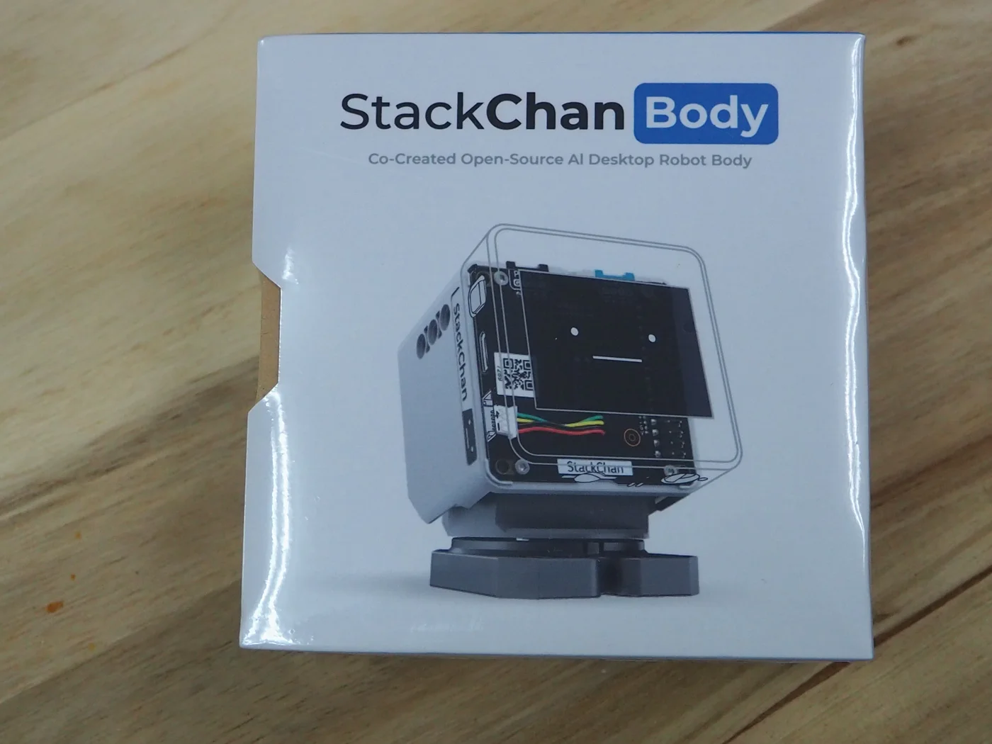
Official StackChan Body Package
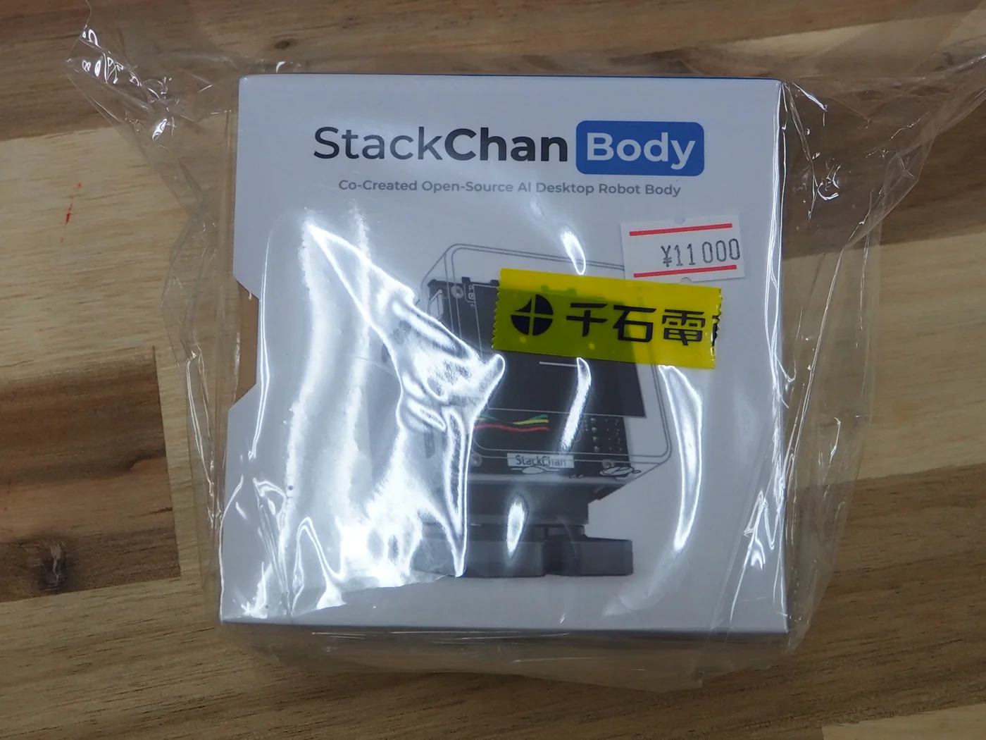
I bought the unit off the shelf at Sengoku Densho in Akihabara for 11,000 JPY (tax included).
The back of the box lists the core hardware specifications.
| Item | Details |
|---|---|
| Model | M5STACKCHAN |
| Servo mechanism | Pan 360° / Tilt 90° PWM servos |
| Built-in features | 13.56 MHz NFC, capacitive touch pad, 12× RGB LEDs |
| Power | 550 mAh LiPo battery built-in, USB Type-C |
| Expansion | Port B / Port C (Grove compatible ports) |
| Certification | Japan MIC ID: 219-269152 |
Inside the box, the unit comes with two hex wrenches of different sizes for assembly and disassembly.
The bottom has anti-slip silicone rubber feet alongside a label displaying the certification mark and NFC antenna location.
Removing the DIN Base from the CoreS3
The CoreS3 had been running with its stock DIN Base attached to the rear.
I used it as a desktop terminal with Grove cables plugged into its rear ports for the Unit Key and Unit CO2L sensor.
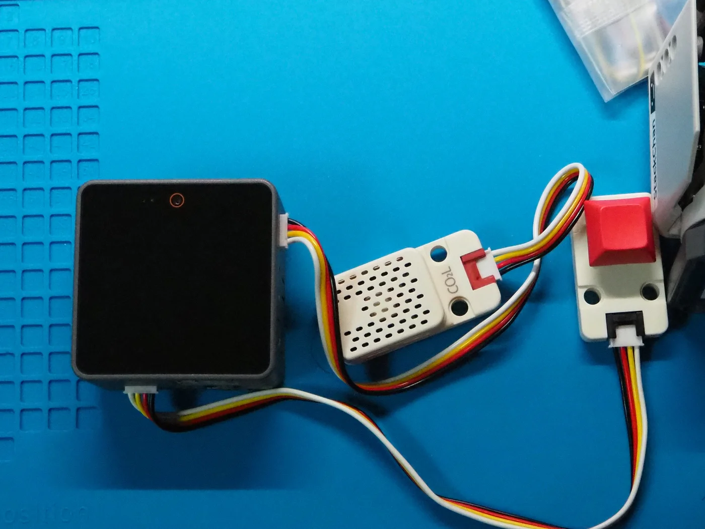
Mounting the CoreS3 into the StackChan Body requires direct connection to the rear board, so the DIN Base had to be removed.
I loosened and removed the two hex bolts on the back using the provided hex wrench.
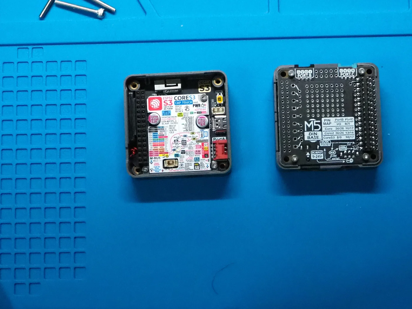
Once the bolts were out, the DIN Base separated and exposed the CoreS3’s female M-Bus connector and internal board.
Connecting the Internal Cable and M-Bus
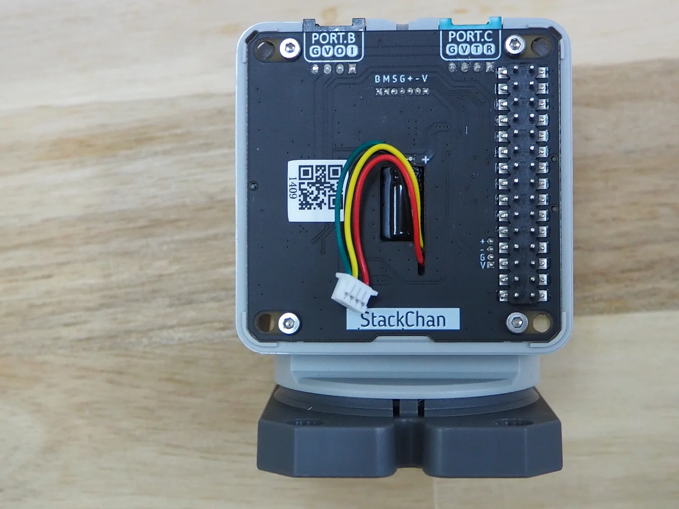
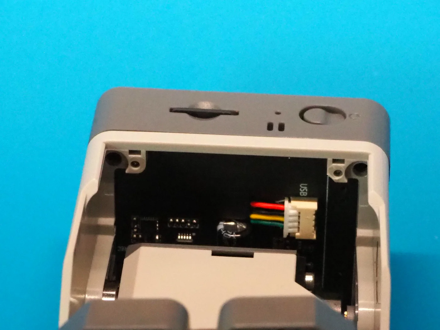
The StackChan Body has male M-Bus pins as well as a 4-wire internal cable (red, yellow, green, white).
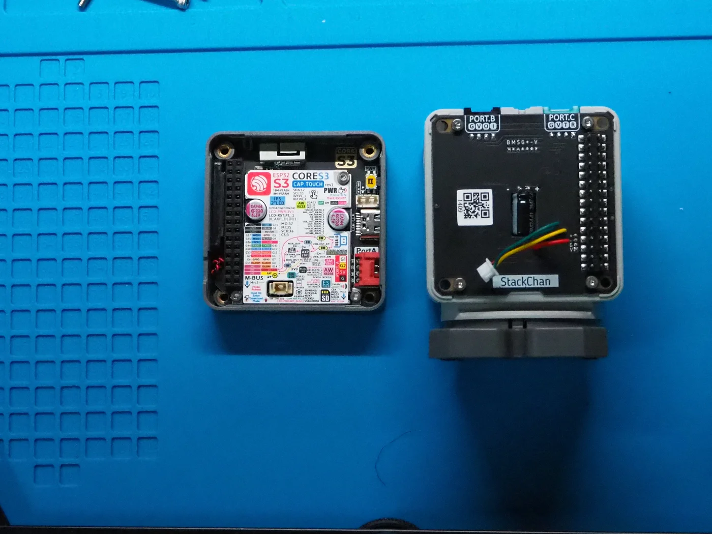
I plugged this small 4-pin connector into the mating receptacle located between the power switch and the Type-C port on the CoreS3 board.
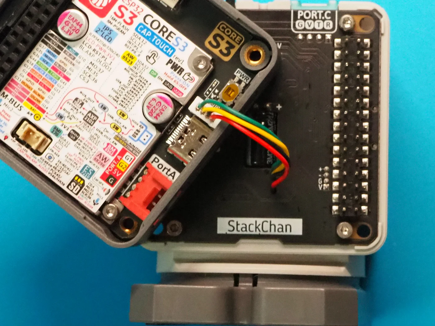
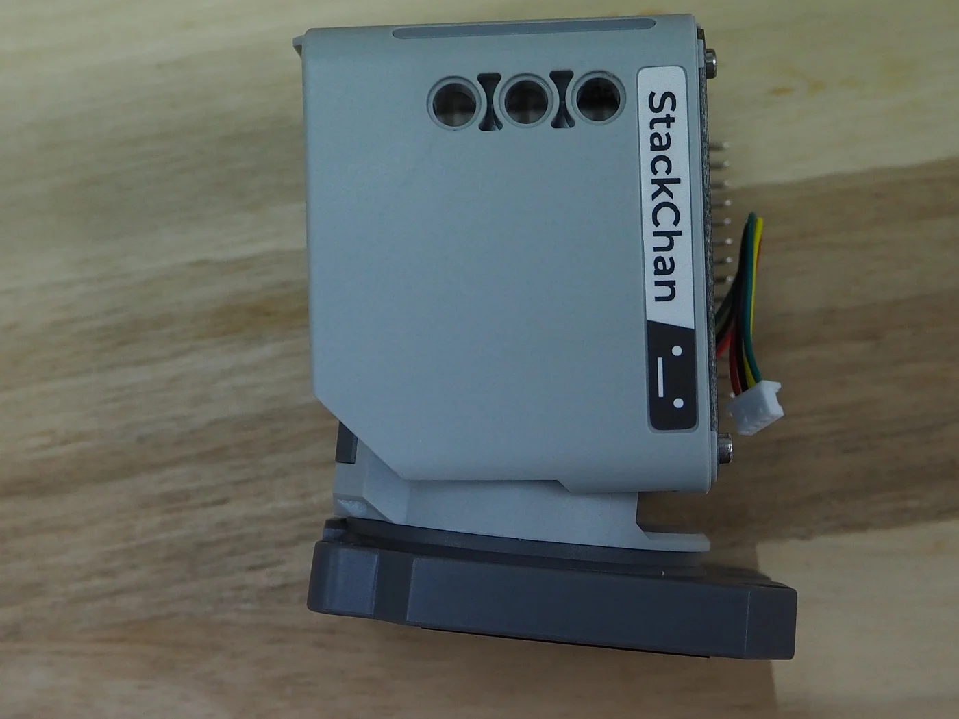
After connecting the cable, I routed the slack wire into the hollow cavity inside the body while aligning the CoreS3 female M-Bus header with the pins on the body.
Pushing it in evenly seated the CoreS3 neatly into the head opening of the StackChan Body.
Tightening the fastening screws completed the assembly into the desktop robot form.
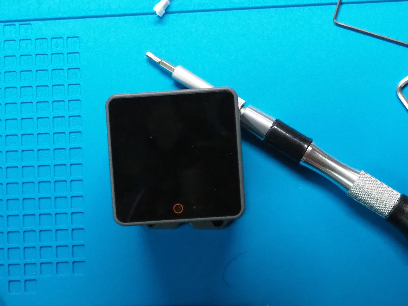
Power-On and Initial Boot Check
With physical assembly complete, I tested the power and initial boot.
I connected a USB cable to the Type-C port on the side of the CoreS3 to supply power.
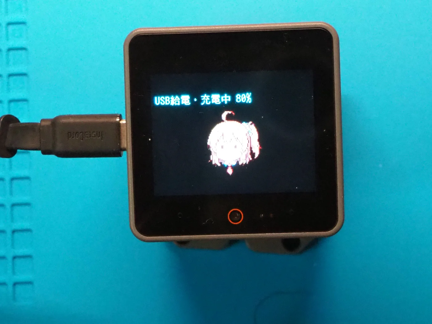
The red indicator around the power button illuminated, and the display turned on.
The previously flashed firmware booted up as expected, displaying the charging status (“USB給電・充電中 80%”) and the idle pixel-art face icon.
The board and display survived the disassembly and transplant without damage. This confirmed that the physical wiring and connector mating were successful.
I have not written any code yet to control the Pan/Tilt servos, the RGB LEDs, the capacitive touch sensors, or the NFC reader.
Writing the control software will be the next step.