Reviving a 100-Yen Junk ACR1251U NFC Reader: Firmware Downgrade & EZ Sign E-Paper Writing on Windows 11
 Contents
I had been looking for an NFC reader when I saw a post on X from Palette Town in Akihabara announcing a junk clearance.
I went over and picked up two units for 100 JPY each (200 JPY total).
At the time of purchase, I had no specific project in mind and figured I would find a use for them later.
Around then, I came across Santek’s EZ Sign, an electronic paper display updated via NFC.
It has no battery, drawing both operating power and image data directly from the NFC radio frequency (RF) field.
Alongside mobile apps, the manufacturer explicitly lists Windows support, allowing updates straight from a PC using an NFC reader.
However, the official manual recommends the Sony RC-S300, with no mention of ACS readers.
If the software talks through standard Windows PC/SC APIs (WinSCard), any compliant reader should work.
If it relies on proprietary RC-S300 extensions, it will fail.
Getting an e-paper display to update with a 100-yen junk reader sounded like a fun challenge.
Hardware Overview
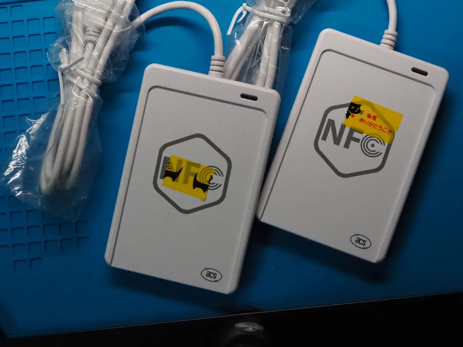
Both units arrived in like-new cosmetic condition.
On one unit, I left the yellow “Thank you very much” checkout tape that the clerk slapped over the NFC logo unpeeled.
The USB cables are hardwired directly into the enclosures.
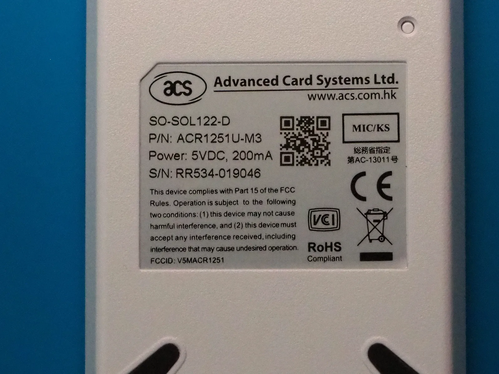
The label on the back of the enclosure lists the following specifications:
| Field | Label Value |
|---|---|
| Model | SO-SOL122-D / P/N: ACR1251U-M3 |
| Power | 5VDC, 200mA |
| S/N | RR534-019046 (unit photographed) |
| Certifications | FCC ID: V5MACR1251, CE, VCCI, MIC AC-13011 |
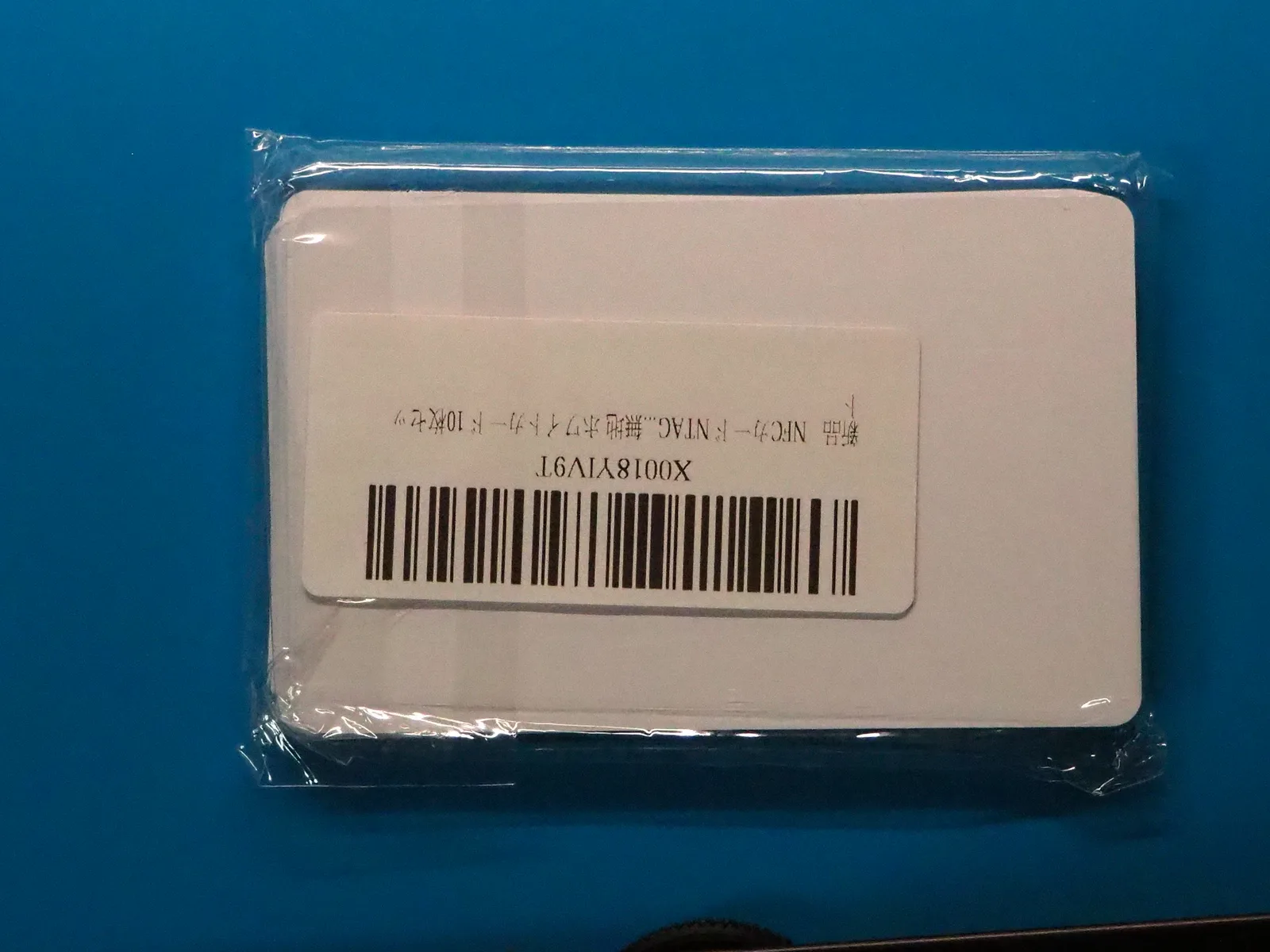
For testing read and write operations, I bought a 10-pack of blank white NTAG cards.
The bag label reads “NFC Card NTAG… Rewritable White Card 10-pack”.
It does not specify whether they contain NTAG213, 215, or 216, so I will need to check the chip type over RF.
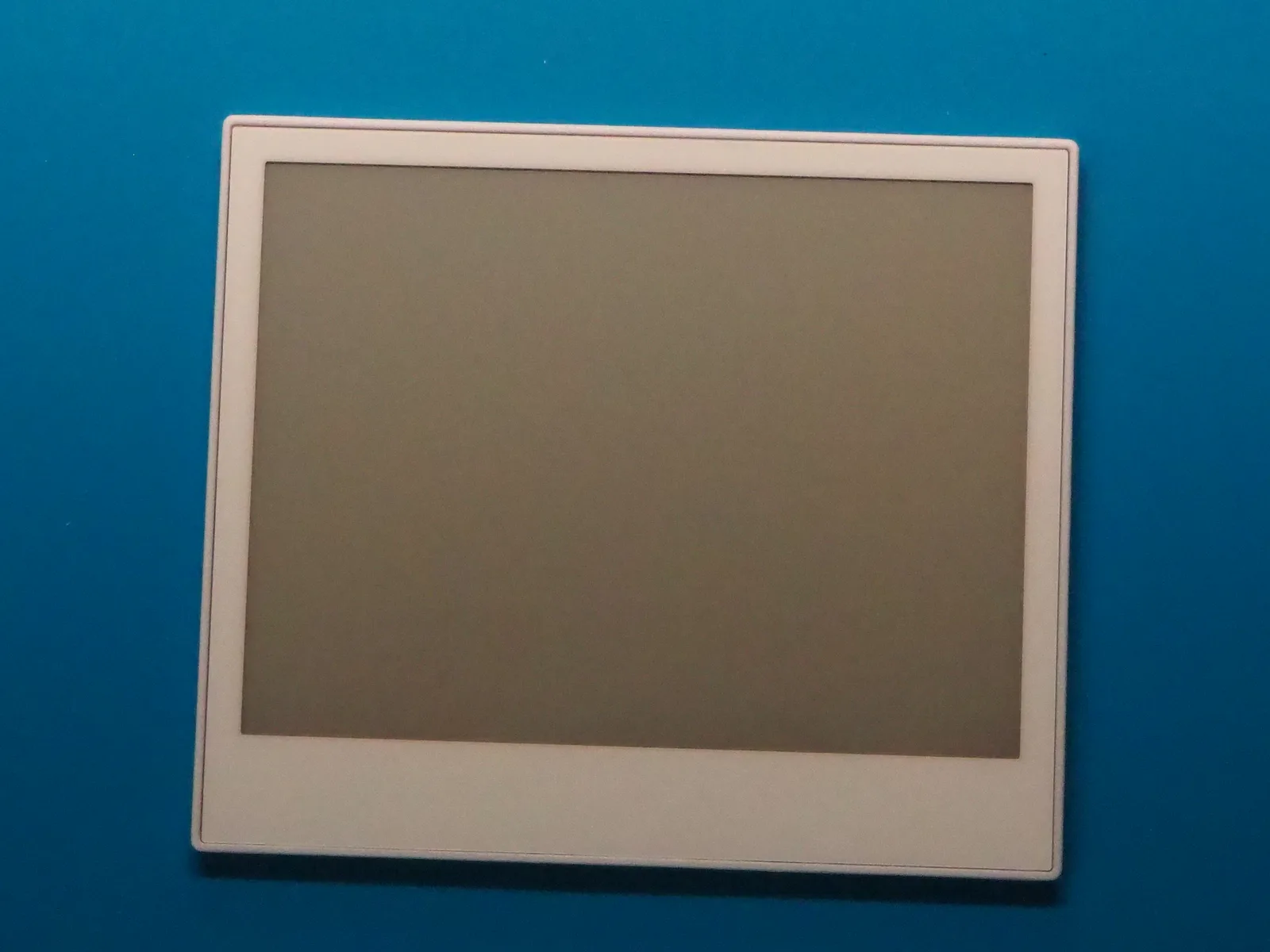
And here is the EZ Sign.
The box is labeled “EZ Sign 4.2 Inch E-Paper Display”, and the back of the panel is embossed with “Santek EZ Sign 4 Color”.
Key product specifications:
| Item | Details |
|---|---|
| Resolution | 400×300 pixels |
| Colors | Black, White, Red, Yellow (4 colors) |
| Refresh time | Approx. 30 seconds |
| Power | Battery-free, powered via NFC RF field. Retains image indefinitely without power |
| Platforms | iOS, Android, Windows |
| Rating | IP65 |
| Thickness | 3.4 mm |
Power delivery is an extra hurdle.
Taking 30 seconds to refresh means the reader must not only speak the right protocol, but also output enough RF energy continuously to keep the display controller alive during the entire write sequence.
Test Environment
| Item | Details |
|---|---|
| Host PC | Windows 11 Home 10.0.26200 |
| PC/SC Service | SCardSvr stopped before test, started manually |
| NFC Readers | ACS ACR1251U-M3 ×2 |
| NFC Cards | Rewritable NTAG blank cards (10-pack) |
| Display Device | Santek EZ Sign 4.2” E-Paper (4-color) |
PC/SC is the standard Windows subsystem connecting smart card readers and host software.
When a compliant reader is plugged in, the SCardSvr service launches and enumerates the device.
All commands in this test were issued via PC/SC.
The verification covers four milestones:
| # | Objective | Pass Criterion |
|---|---|---|
| 1 | Device recognition | Reader name appears in PC/SC device list |
| 2 | Card detection | Read card UID and identify NTAG IC model |
| 3 | Read/write memory | Write payload to card and verify read-back |
| 4 | EZ Sign update | Successfully refresh the e-paper image |
The first step is verifying reader recognition.
If the OS cannot see the reader cleanly, diagnosing card communication issues becomes impossible.
Initial USB Recognition
The device was recognized immediately without installing third-party drivers.
Before connecting, PowerShell’s Get-PnpDevice -Class SmartCardReader returned 0 items, and SCardSvr was stopped.
Plugging one reader into a USB port started SCardSvr automatically, adding one device under the SmartCardReader class.
| Property | Value |
|---|---|
| Device Name | Microsoft Usbccid Smartcard Reader (WUDF) |
| Hardware ID | USB\VID_072F&PID_222D&REV_0541 |
| USB Product String | ACR122U for NFC |
| PC/SC Reader Name | ACS ACR122U for NFC 0 |
| Status | OK |
Windows applied its built-in generic Usbccid driver.
USB CCID is a standard device class specification for smart card readers, allowing compliant hardware to work across operating systems without vendor drivers.
The Vendor ID (VID) 072F corresponds to ACS, matching the physical label.
However, both the USB product string and the PC/SC reader name reported “ACR122U”.
The label on the back reads ACR1251U-M3, creating an immediate contradiction between the hardware label and the USB descriptor.
To check the internal firmware version, I sent the ACS escape command (FF 00 48 00 00) directly to the reader without a card.
All three standard control codes (IOCTLs) returned rc=0x00000001, failing with Win32 ERROR_INVALID_FUNCTION.
Escape commands allow applications to send low-level vendor-specific commands through PC/SC, but Microsoft’s default Usbccid driver disables direct escape routing by default for security and stability.
I set the identity discrepancy aside for a moment to test reading a card.
Both the ACR122U and ACR1251U support ISO 14443 Type A, so basic NTAG communication should work regardless of the exact model.
Testing Card Read Operations
I placed an NTAG card onto the reader and queried the card state via PC/SC.
| Property | Value | Meaning |
|---|---|---|
| eventState | 0x00020422 | Card detected (PRESENT) but unpowered (UNPOWERED) |
| ATR | 3B 00 | 2 bytes (minimal stub) |
The ATR (Answer to Reset) is the initial byte sequence returned by a smart card when energized by the reader’s RF field, identifying the card type and protocol parameters.
A functioning ISO 14443 Type A NTAG card should return an informative ATR roughly 20 bytes long.
The 3B 00 sequence here is an empty stub indicating that the reader obtained no meaningful data from the card.
Calling SCardConnect succeeded, but that only indicates the software channel between the PC and the reader opened; it does not mean the card was powered on or initialized.
Every APDU command sent to the card failed with SW=63 00:
| APDU | Function | Target |
|---|---|---|
FF CA 00 00 00 | Get UID | Query unique card ID from reader |
FF CA 01 00 00 | Get ATS | Query card protocol parameters |
FF B0 00 00 10 | Read pages 0–3 | Read memory block |
FF B0 00 04 10 | Read pages 4–7 | Read memory block |
Commands beginning with FF are PC/SC pseudo-APDUs processed by the reader firmware rather than the card itself.
The trailing status word (SW) returns 90 00 on success and non-9000 on errors or warnings.
Receiving 63 00 across all attempts meant the reader was completely unable to establish contact with the tag.
Because the PRESENT flag was set, I initially suspected the reader saw the card physically but failed during the RF boot handshake.
Investigating the Ghost Card Detection
I ran several tests adjusting physical conditions.
The first unit still had the yellow checkout sticker over the NFC logo, but a thin paper sticker cannot block 13.56 MHz magnetic induction.
Swapping to the second unit, which had no sticker, produced the exact same behavior.
| Condition Change | Result |
|---|---|
| Reposition card directly on center and press down | No change |
| Swap to 2nd reader without sticker | No change |
| Replace NTAG card with Japanese My Number card | No change |
| Remove all cards completely | No change |
Even with nothing on the reader, PRESENT was still returned.
The initial assumption that “a card was detected” was completely false.
On a normal reader, the state is EMPTY when idle, switching to PRESENT + POWERED with a valid ATR only after a card enters the field.
These units reported a constant phantom card stuck in PRESENT + UNPOWERED with 3B 00, regardless of whether a card was present.
Had I not tested the reader completely empty, I would have wasted hours debugging card placement and individual tag defects.
The second unit shared the exact same hardware ID (USB\VID_072F&PID_222D&REV_0541) and product string (ACR122U for NFC).
Neither unit contains a unique serial number in its USB descriptor.
Plugging them into the same USB port produced identical Windows device instance IDs, making them indistinguishable in Device Manager.
At this point, the core problem became clear: “being recognized as a reader by Windows” and “communicating with a contactless card over RF” belong to entirely different layers.
flowchart TD
    subgraph Host["Host PC (Windows)"]
        App["Application / Script"]
        SCardSvr["Smart Card Service<br/>(SCardSvr)"]
        Driver["USB CCID Driver<br/>(Usbccid / ACS Proprietary)"]
        App -->|"PC/SC API (WinSCard)"| SCardSvr
        SCardSvr --> Driver
    end

    subgraph Device["NFC Reader (ACR1251U)"]
        MCU["Reader MCU / Firmware"]
    end

    subgraph Target["Target Device"]
        Card["NFC Card / EZ Sign"]
    end

    Driver -->|"USB Communication"| MCU
    MCU -->|"13.56 MHz RF Field (Power & Data)"| Card
Both readers were recognized by Windows and accepted host commands, but card detection was completely dead.
Because the issue persisted across both units regardless of card type or presence, I began systematic isolation across drivers, register settings, power delivery, and firmware.
Testing Official ACS Drivers
The official product pages for both the ACR1251U and ACR122U offer the same “ACS Unified PC/SC Driver 4.2.8.0” (released March 2018 in RAR format).
Before running the installer, I extracted the MSI to inspect acsdrv.inf.
An INF file maps USB hardware IDs to driver binary configurations.
While acsdrv.inf lists over 70 PIDs for VID 072F, the PID of my hardware (222D) is missing:
| PID | INF Mapping |
|---|---|
| 2200 | ACR122U |
| 2218 | ACR1251U-C (PICC / SAM) |
| 2229 | ACR1251U-A2 |
| 222C | ACR1283L PICC |
| 222D | Not listed |
| 222E | ACR123-PICC+3SAM Bus |
222C and 222E exist, but 222D is skipped.
Conversely, the open-source Linux/macOS driver acsccid lists 072F 222D under an unnamed [OEM Reader] entry.
Installing the package registered oem263.inf in Windows, but the device stayed on wudfusbcciddriver.inf.
Without a matching hardware ID, Windows correctly refused to bind the proprietary driver automatically.
This ghost card behavior has precedent.
A blog post from an engineer who bought a 100-yen junk Maxell-branded ACR122U at Book-Off described the exact same symptoms: “reports card present when empty” and “returns static values regardless of card presence.” That investigation was abandoned without a resolution.
Manual Driver Binding and Identifying the Model
In Device Manager, I uncheked “Show compatible hardware” and manually assigned the driver for manufacturer “Advanced Card Systems Ltd.”, model “ACR122 Smart Card Reader”.
Manually forcing a driver intended for different hardware carries risks, but having a second unit on hand for recovery made this experiment safe to try.
Windows threw compatibility warnings, but the driver installed.
With the ACS driver active, the previously blocked escape commands started working.
Sending FF 00 48 00 00 over escape IOCTL 3500 returned an ASCII string:
ASCII: ACR1251U_V541.00The underlying hardware is an ACR1251U, matching the exterior label.
The REV_0541 in the USB hardware ID corresponds to firmware version V541.00.
The device is an OEM model reporting PID 222D and descriptor string ACR122U for NFC, while the physical label on the case accurately reflected the true hardware inside.
With escape routing working, I queried the reader’s internal parameters:
| Parameter | Command | Response | Meaning |
|---|---|---|---|
| Firmware version | E0 00 00 18 00 | ACR1251U_V541.00 | ACR1251U family |
| PICC operating params | E0 00 00 20 00 | 07 | Type A / Type B / Topaz enabled |
| Auto PICC polling | E0 00 00 23 00 | 8F | Polling enabled |
| Antenna status | E0 00 00 25 00 | 00 | Disabled (Off) |
With the antenna off, card detection and RF power transfer are impossible.
Sending E0 00 00 25 01 01 enabled the antenna, changing the query response to 01.
Even with the antenna enabled, card detection remained dead.
The ATR stayed at 3B 00, and UID queries still returned SW=63 00.
Toggling the antenna register did not solve the issue.
Re-binding to the ACR1251U Driver Section
Since the hardware was confirmed as an ACR1251U, binding it to the ACR122U section might have misconfigured the contactless slot interface.
I repeated the manual assignment, this time selecting “ACR1251 CL Reader PICC”.
The reader name changed to ACS ACR1251 CL Reader PICC 0, but the ATR and APDU responses remained unchanged.
Scanning configuration registers from 0x10 through 0x40 via E0 00 00 xx 00 revealed several valid responses:
| Register | Command | Response | Meaning |
|---|---|---|---|
| Firmware | E0 00 00 18 00 | ACR1251U_V541.00 | Firmware identifier |
| PICC params | E0 00 00 20 00 | 07 | Enabled protocols |
| Polling setting | E0 00 00 21 00 | 8F | Polling interval |
| Auto polling | E0 00 00 23 00 | 8F | Auto-detect enabled |
| Antenna status | E0 00 00 25 00 | 01 | Antenna active |
| RF registers | E0 00 00 2F 00 | 11 85 85 85 85 A5 A5 A5 A5 69 … | RF transceiver tuning |
| Thresholds | E0 00 00 3F 00 | 2F 55 69 3F 2F 55 69 3F | Receive threshold levels |
The microcontroller (MCU) and USB interface responded cleanly, reading and updating register values.
Yet contactless card detection remained completely unresponsive, with no register showing an explicit disable bit.
Direct Control of LEDs and Buzzer
I next inspected the physical behavior of the unit.
ACS readers typically beep on card detection by default, but this unit stayed silent when cards were placed.
The LED blinked continuously regardless of card presence.
According to the official ACR1251U Technical Specifications V1.11, the LED and buzzer are driven directly by host commands.
Blinking is not necessarily an error code.
By issuing direct control commands, I could determine whether the buzzer was physically broken or simply never commanded to fire.
| Action | Command | Response | Observed Hardware Behavior |
|---|---|---|---|
| LED Red | FF 00 40 50 04 00 00 00 00 | 90 00 | Solid red illumination |
| LED Green | FF 00 40 A0 04 00 00 00 00 | 90 00 | Solid green illumination |
| LED Blink + Beep | FF 00 40 D0 04 05 05 04 03 | 90 02 | Brief color flash, zero sound |
| LED Off | E0 00 00 29 01 00 | 01 00 | LED turned off |
The LED tracked host commands perfectly.
However, the buzzer remained silent even under direct activation commands.
It is either physically defective or was omitted from the PCB on this OEM build.
Given the OEM model number SO-SOL122-D, it is possible this variant was manufactured without buzzer or antenna circuitry.
Opening the case would settle this immediately, but the enclosure has no visible screws or seam gaps.
To avoid destroying the plastics, I left the shell intact.
Verifying the Second Unit and Direct USB Power
I plugged the second unit into the same USB port.
Because it lacks a unique serial number, it inherited the instance ID and ACS driver mapping from the first unit:
| Item | Unit 2 State |
|---|---|
| Firmware | ACR1251U_V541.00 (identical) |
| Initial antenna state | 00 |
| Antenna after enable | 01 |
| Card read result | ATR 3B 00, SW=63 00 |
The initial antenna state read 00, confirming that the 01 written to the first unit persisted in its local volatile memory.
Unit 2 behaved identically in every respect.
The LED behavior also transitioned identically.
Immediately after setting the antenna register to 01, the LED switched to solid light, before returning to blinking after a timeout.
Since register writes and LED commands execute properly, the host MCU is functioning normally.
I also checked power delivery.
Up to this point, the reader was plugged into a docking station.
The ACR1251U is rated at 5VDC 200mA, and generating high-frequency 13.56 MHz RF fields consumes substantial current.
If the hub’s power rail sagged, the MCU might boot while the RF transmitter dropped offline.
I plugged the reader directly into a motherboard USB port on the PC.
Moving to a new port generated a new instance ID, requiring driver re-assignment.
The results were unchanged, ruling out insufficient USB supply current.
Verifying the RF Field with a Smartphone
Up to this point, I knew cards were not detected, but could not distinguish whether the reader failed to emit an RF field or emitted a field but failed to receive replies.
Relying solely on reader self-reports was insufficient; I needed an external sensor.
A smartphone serves this role well.
NFC-equipped phones react when entering an external magnetic field.
Placing a phone over the reader provides an independent check of the 13.56 MHz carrier wave.
First, I tested two unverified commands:
| Command Tested | Result |
|---|---|
Read/write E0 00 00 40 | Empty response (register does not exist) |
PN532 direct command FF 00 00 00 02 D4 32 | 63 00 (Expected; ACR1251U is not PN532-based) |
Next, I held the antenna in the enabled state for 10 seconds and laid an NFC phone flat on the reader with its wallet app open.
There was zero reaction: no wallet screen, no haptic vibration, and no detection chime.
Despite the antenna register returning 01, the reader was not emitting a 13.56 MHz RF field.
Either the RF output stage was physically damaged, or the running firmware was not driving the oscillator.
Triggering Bootloader Mode with the Rear Switch
On the back of the case sits a small recessed switch.
Pressing it while running in normal mode caused no state changes in PC/SC.
However, the ACS INF file includes a device definition named ACR1281 USB FW_Upgrade v100.
Many ACS readers enter bootloader mode if powered on while holding a physical button.
I held the switch down, inserted the USB cable, waited three seconds, and released it.
| Property | Normal Mode | Bootloader Mode |
|---|---|---|
| Hardware ID | USB\VID_072F&PID_222D | USB\VID_072F&PID_220B |
| Device Name | ACR1251 CL Reader PICC | ACR1281 USB FW_Upgrade v100 |
| Card Status | PRESENT + UNPOWERED | EMPTY |
| ATR | 3B 00 | None (cbAtr=0) |
The hidden switch is a firmware bootloader trigger.
In this mode, the reader correctly reported card status as EMPTY.
The perpetual phantom card was generated entirely by the V541.00 runtime firmware.
The hardware was not broken; the firmware loaded on this OEM unit was actively failing to drive the contactless subsystem.
Because I had two identical units, I decided to flash one unit with alternate firmware while preserving the other on V541.00 as a reference baseline.
Finding Firmware Images
ACS does not publicly host firmware binaries or update utilities.
The 13 public utility downloads on their site contain no firmware files, and the Wayback Machine yielded no archived historical packages.
Official updates require opening a support ticket.
Searching broader OEM distribution channels turned up a package from NTT Communications.
NTT distributed OEM ACR1251 readers for Japan’s Public Certification Service and provided firmware update packages on a public download page without registration.
The download contained the official “ACR1251 FW Update Tool” alongside encrypted Patch/Patch.hex payloads:
| Package | Target Firmware |
|---|---|
| ACR1251CL_FW431.2.zip | 431.2 |
| ACR1251DI_FW713.0.zip | 713.0 |
| ACR1251DI_FW721.1.zip | 721.1 |
Across all three archives, the tool executable was byte-for-byte identical; differences were limited to InitFile.ini and Patch/.
Strings inside the executable revealed Tool for update ACR1251U-M2 and ACR1251U-C4 Firmware, ACS ACR1281 USB FW_UPGRADE V100, READER_AES_KEY, and ReaderAuth.
The string matches the bootloader device name discovered earlier.
This also clarified the true lineage of my hardware.
The acsccid driver source defines:
# ACR1251U-A2
0x072f:0x222d:ACS ACR122U
ACS defined 222D internally as an OEM ACR1251U-A2 reporting as an ACR122U.
This explained why the label said ACR1251U-M3, the firmware reported ACR1251U_V541.00, and the USB descriptor read ACR122U for NFC.
The driver model I had manually bound (“ACR1251 CL Reader PICC”, PID 2229 for ACR1251U-A2) was the correct assignment.
I also extracted the newer ACS 4.4.2.1 driver installer (December 2025) to check its INF.
PID 222D was absent there as well.
I did not install the driver, but its ReadMe noted 072F 2229 ACR1251U-A2/M2 ACS ACR1251 CL Reader PICC, confirming again that PID 2229 is the standard retail equivalent.
Replaying NTT Initialization APDUs
The NTT package’s Patch/Init.txt contains the sequence of APDUs written to the reader post-flash.
They use the standard E0 00 00 xx escape format, meaning they can be sent directly to the reader without flashing.
Comparing these values against my unit showed clean separation between matches and divergences:
| Register | NTT CL 431.2 Value | Unit Value |
|---|---|---|
2F (RF tuning) | 11 85 85 85 85 A5 A5 A5 A5 69 … | Exact match |
3F (Thresholds) | 2F 55 69 3F 2F 55 69 3F | Exact match |
20 (PICC params) | 1F | 07 |
21 | 57 | 8F |
23 (Auto polling) | 8B | 8F |
The RF transceiver register dump matched byte-for-byte, confirming the physical RF layout is identical to the CL (ACR1251U-A2) board.
However, the operational polling registers differed.
The 07 in register 20 only enables Type A, Type B, and Topaz, whereas NTT’s default 1F enables FeliCa 212/424 as well.
Because register writes can be undone, I pushed the complete NTT initialization sequence to the reader.
All commands succeeded and read back accurately:
| Register | Before | After |
|---|---|---|
08 | FF FF | 11 FF |
20 | 07 | 1F |
21 | 8F | 57 |
23 | 8F | 8B |
24 | 00 00 00 00 | 02 00 02 00 |
Still, cards were not detected.
Furthermore, power-cycling the reader restored 20 to 07 and 23 to 8F.
These settings live in volatile RAM rather than EEPROM, resetting on every cold boot.
Fixing the reader via register manipulation was a dead end.
Flashing Tool Device Discovery Errors
Flashing the firmware was the only remaining path.
However, my hardware was running 541.00, while the NTT CL package provided 431.2.
The Patch.hex payload is encrypted, and the utility uses hardcoded READER_AES_KEY and ReaderAuth handshakes.
This is a cryptographically signed OEM update mechanism, not a raw flash dumper.
Before attempting to flash, I ran the tool to check device enumeration.
The UI presented a minimal interface:
| Field | Display |
|---|---|
| Reader Model | ACR1251CL-NTTCom |
| Reader Selection | Dropdown (1 item) |
| Buttons | Refresh / Update |
The tool displayed neither the current nor target firmware version.
The dropdown contained a single entry: ACS ACR1251 USB FW_UPGRADE V100 0.
My unit in bootloader mode reported ACS ACR1281 USB FW_Upgrade v100 0—differing by one digit (“1251” vs “1281”).
I assumed the tool did not discover the reader dynamically and was populating hardcoded string constants.
Looking for string matches, I searched the binary for UTF-16 strings:
0x00AF92  ACS ACR1281 USB FW_UPGRADE V100
0x00AFD2  ACS ACR1251 USB FW_UPGRADE V100
Both strings are 31 characters long.
I created a copy of the executable and patched both occurrences to match the reader’s runtime name.
The dropdown now listed ACS ACR1281 USB FW_Upgrade v100 0, and disconnecting the reader cleared the list on refresh, proving enumeration was dynamic.
I also tested launching from normal mode.
The binary contains the string Run Change to Upgrade Mode, indicating the utility can switch a normal-mode reader into the bootloader automatically.
The normal-mode name ACS ACR1251 CL Reader PICC 0 appeared in the original unpatched tool’s dropdown as well.
Yet across all four permutations, clicking “Update” immediately threw a “Reader search error”:
| Executable | Mode Supplied | Result |
|---|---|---|
| Original | Bootloader | Search Error |
| Original | Normal | Search Error |
| Patched | Bootloader | Search Error |
| Patched | Normal | Search Error |
The tool selected the reader cleanly in the dropdown, but crashed inside the update subroutine before flash communication began.
The patched strings were not what the update loop was using.
Decompiling the Flashing Utility
Disassembling the binary was far more reliable than blind string editing.
Because the utility is a .NET assembly, it decompiles cleanly.
Without the .NET SDK installed on this host, I grabbed the ICSharpCode.Decompiler package from NuGet and invoked it via PowerShell.
The decompilation revealed that the tool natively supported the ACR1281 string from day one:
else if (Mid(array2[i].ToUpper(), 0, "ACS ACR1281 USB FW_UPGRADE V100".Length)
         == "ACS ACR1281 USB FW_UPGRADE V100".ToUpper())
{
    cmbICC.Items.Add("ACS ACR1251 USB FW_UPGRADE V100" + array2[i].Substring(...));
}
When the tool sees an ACS ACR1281 … reader, it cosmetically rewrites the display string to ACS ACR1251 … in the UI, mapping it back upon selection.
The string ACS ACR1251 USB FW_UPGRADE V100 0 seen earlier was not a static placeholder; it was my real device.
My string-replacement patch had actually broken the comparison logic.
The actual blocker was a firmware version check.
Before flashing, the tool queries the reader with E0 00 00 18 00 and parses the version:
text  = ASCII.GetString(array, 5, 7);            // "ACR1251"
text2 = ASCII.GetString(array, 15, len - 15);    // "541.00"
num   = Convert.ToInt32(text2.Substring(0, 3), 16);   // 0x541
// C4 build requires: (num & 0x700) == 0x700 (7xx branch)
// M2 build requires: (num & 0x700) == 0x400 (4xx branch)
My unit reported 0x541 & 0x700 = 0x500, matching neither rule.
The utility applies a bitmask (& 0x700) to the major hexadecimal digit to determine the firmware branch.
Because InitFile.ini maps Reader#ACR1251CL-NTTCom# to the M2 build, it requires the 4xx branch (0x400).
The error was caused by an incompatible firmware family, not a device name mismatch.
This also explained why starting directly in bootloader mode failed.
Immediately after verifying the firmware version, the tool issues an escape command instructing the normal-mode firmware to reboot into the bootloader.
If the device is already in bootloader mode, that command fails.
Consequently, running in normal mode failed the version check, while running in bootloader mode failed the reboot command.
The AES keys inside the binary were fixed constants: READER_AES_KEY and PC_AES_KEY are hardcoded across all units.
The cryptographic handshake would succeed once the gating checks were satisfied.
Patching the 1-Byte Version Check
To bypass the check, I needed to alter the branch comparison.
The relevant IL sequence is ldc.i4 0x700, and, ldc.i4 0x400.
In a fresh copy of the utility, I patched the final constant from 0x400 to 0x500.
This required modifying a single byte (20 00 07 00 00 5F 20 00 04 00 00 → ... 05 ...) at offset 0x003927.
Modifying binaries and cross-flashing firmware carries the risk of permanently bricking hardware; this was an experimental procedure performed on a disposable unit.
Starting the reader in normal mode and clicking “Update” now popped up a confirmation dialog:
Current Version: 541.00
Update Version: 431.2 (Downgrade)
Do you want to proceed?
The utility read the real firmware version directly from the device.
Clicking “Yes” triggered the automatic bootloader transition, authenticated the session, flashed the payload, and completed successfully.
| Property | Before Flash | After Flash |
|---|---|---|
| USB PID | 222D (Unnamed OEM) | 2229 (Retail ACR1251U-A2) |
| Firmware Version | ACR1251U_V541.00 | ACR1251U_V431.2 |
| PICC Parameters | 07 | 1F |
| Auto PICC Polling | 8F | 8B |
| Serial Number | Empty | Valid string returned |
The PID changed from 222D to 2229 because the newly flashed firmware reports itself as a standard retail ACR1251U-A2.
This was not merely a register change; the operating system now recognized the device as authentic hardware.
Unlike manual register writes, the updated configuration persisted across power cycles.
The flashing procedure and PowerShell scripts used throughout this test are published in the LiltingChannelLabo repository.
Because the firmware and tools are proprietary, users must download the original archive directly from NTT’s distribution site.
Reading NTAG Cards
I placed an NTAG card onto the newly flashed reader:
ATR  : 3B 8F 80 01 80 4F 0C A0 00 00 03 06 03 00 03 00 00 00 00 68
UID (FF CA 00 00 00)   SW=90 00  DATA=04 74 9C 82 20 24 90
page 00-03             SW=90 00  DATA=04 74 9C 64 82 20 24 90 16 48 00 00 E1 10 3E 00
page 04-07             SW=90 00  DATA=03 00 FE 00 00 00 00 00 00 00 00 00 00 00 00 00
The ATR returned in standard PC/SC storage card format (ISO 14443A part 3).
The leading 04 in the UID identifies NXP manufacturing.
NTAG memory is organized into 4-byte pages.
Pages 0 through 3 store the UID, internal manufacturer data, and the Capability Container (CC), while user memory starts at page 4.
The CC at page 3 (E1 10 3E 00) defines tag capacity.
Multiplying the size byte 0x3E (62 decimal) by 8 gives 62 × 8 = 496 bytes of available NDEF memory.
This confirmed the mystery cards as NTAG215.
Page 4 containing 03 00 FE indicates an unwritten, empty NDEF container.
The hardware LED also changed behavior.
Before flashing, the LED blinked rapidly regardless of card presence.
Now, it illuminates solid when a card is present and pulses slowly when idle, proving the previous blinking was an error indicator.
Writing and Reading Back NDEF Data
I formatted a URI NDEF record pointing to https://lilting.ch/ and wrote it starting at page 4.
Writing to NTAG uses 4-byte page units via FF D6 00 <page> 04 <data>:
| Page | Written Value |
|---|---|
| 04 | 03 10 D1 01 |
| 05 | 0C 55 04 6C |
| 06 | 69 6C 74 69 |
| 07 | 6E 67 2E 63 |
| 08 | 68 2F FE 00 |
Every page write returned SW=90 00.
Reading back the data verified the payload:
page 04-07 : 03 10 D1 01 0C 55 04 6C 69 6C 74 69 6E 67 2E 63
page 08-0B : 68 2F FE 00 00 00 00 00 00 00 00 00 00 00 00 00
The byte structure breaks down as follows: 03 is the NDEF TLV tag, 10 indicates a 16-byte payload, D1 01 0C 55 is the URI record header, 04 is the protocol abbreviation code for https://, the next 11 bytes represent lilting.ch/ in ASCII, and FE is the terminator TLV.
Testing against a smartphone yielded no pop-up notification.
Because the payload verified cleanly over PC/SC, this was likely due to phone antenna alignment rather than a tag error.
Verification with Japanese My Number Cards
NTAG is an ISO 14443 Type A memory tag, representing only one card family.
To verify dual-interface compliance, I tested a Japanese My Number card (ISO 14443-4 contactless CPU card), which had failed during earlier testing.
Monitoring reader events over 15 seconds produced immediate recognition:
[PRESENT] ATR = 3B 88 80 01 00 4B 51 FF B3 81 D1 00 0FA genuine ATR was returned, and querying the UID succeeded with SW=90 00.
Memory page read commands (FF B0) failed with SW=63 00, which is expected behavior: FF B0 is intended for storage cards and is rejected by ISO 14443-4 CPU cards.
Receiving a valid ATR and UID proved the reader handles standard smart cards properly.
When empty, the reader reported EMPTY with cbAtr=0.
The phantom card bug was completely resolved.
Interfacing with the Santek EZ Sign
With the reader operational, I placed the EZ Sign on the platform.
Because it is a battery-free display powered by NFC induction, it should enumerate as a standard contactless card.
The panel was recognized immediately:
| Property | Value |
|---|---|
| ATR | 3B 86 80 01 90 DE 33 01 1E 03 66 |
| UID | DE 33 01 1E |
| ATS | 0B 78 00 A0 02 90 DE 33 01 1E 03 |
| Class | ISO 14443-4 Type A, max frame 256 bytes |
An ISO 14443-4 interface means the display communicates via APDUs.
Standard discovery APDUs elicited responses consistent with an NFC Forum Type 4 Tag.
Type 4 tags structure NDEF data into virtual files: the host selects the NDEF application, queries the Capability Container (CC), and accesses the NDEF data file:
SELECT NDEF App (D2760000850101)  SW=90 00
SELECT CC (E103)                   SW=90 00
READ CC                            00 0F 20 01 00 00 FA 04 06 E1 04 01 F4 00 00
Parsing the CC file revealed:
| Field | Value |
|---|---|
| Mapping Version | 2.0 |
| NDEF File ID | E104 |
| Max NDEF Size | 500 bytes |
| Read Access | 00 (Unrestricted) |
| Write Access | 00 (Unrestricted) |
| Current NDEF Length | 0 bytes |
Write permissions were open.
I attempted to write an NDEF text record to test whether the display would refresh:
| Command | Response |
|---|---|
| Clear NDEF length to 0 | SW=6A E1 |
| Write NDEF payload | SW=90 00 |
| Set NDEF length to 17 | SW=6A E2 |
| Read back length | Length remained 0 |
The data payload was accepted, but updating the length field was rejected.
Without an updated length header, the payload is invalid to readers.
Furthermore, 6A E1 and 6A E2 are non-standard ISO 7816 error codes, indicating custom firmware handling on top of Type 4 emulation.
The display did not change.
Data volume makes this divergence obvious.
A 400×300 4-color image requires 2 bits per pixel, translating to 400 × 300 × 2 ÷ 8 = 30,000 bytes of raw image data.
This is two orders of magnitude larger than the 500-byte NDEF boundary.
Image updates clearly bypass standard NDEF structures.
To map the display’s command set, I fuzzed the CLA and INS bytes, excluding destructive standard operations like erase and format:
| CLA | INS | Response |
|---|---|---|
| 00 | 20 | 6A86 (VERIFY: Incorrect P1/P2) |
| 00 | 84 | 6700 (GET CHALLENGE: Invalid length) |
| 00 | B0 | 6986 (READ BINARY: No file selected) |
| 00 | D1 | 9000 + Data payload |
| 00 | D5 | 9000 + 00 |
Instruction INS=D1 returned TLV-encoded hardware descriptors:
A0 07 F0 07 20 02 58 01 90
A1 07 01 12 00 30 FF FF FF
B1 01 08
B2 01 14
B3 01 00
C0 0A 53 45 41 42 ...        ← ASCII Serial Number
C1 04 DE 33 01 1E            ← Matches Card UID
D1 07 01 20 00 00 00 00 00
Tag C1 matches the card UID, confirming the TLV layout.
Tag C0 holds the ASCII serial number, while A0 embeds 02 58 (600) and 01 90 (400).
INS=D5 returned 00, functioning as a status ping.
Further sweeps with data payloads revealed that image transmission commands are locked behind authentication:
| Command | Response |
|---|---|
00 84 00 00 08 | 9000 + 8 bytes pseudo-random |
00 84 00 00 20 | 9000 + 32 bytes pseudo-random |
00 20 00 01 00 | 6700 (Data required) |
00 20 00 80 / 00 81 / 01 00 | 6A86 |
GET CHALLENGE returned entropy matching the requested length, while VERIFY returned “insufficient data” specifically when P2=01.
The display requires a challenge-response authentication handshake before unlocking write commands.
| Communication Layer | Status |
|---|---|
| ISO 14443-4 | Operational (accepts APDUs) |
| NFC Forum Type 4 / NDEF | Operational (E104 500-byte container) |
| Proprietary Hardware TLVs | Accessible via INS=D1 and INS=D5 |
| Authentication | GET CHALLENGE functions, but key is unknown |
| Image Refresh | Blocked behind challenge-response gate |
While manual image transfer was blocked by the authentication requirement, the underlying mechanism was identified.
Updating the Display with the Official Software
Santek provides a Windows utility on its website (v1.4.0 on the Japanese portal).
The downloaded installer was signed with a valid EV certificate issued to San Technology (Zhuhai) Co., Ltd., matching the publisher name stated in official documentation.
The utility installs into %APPDATA%\San Technology, Inc\EZ Sign(TM) NFC\.
It is a Flutter desktop application.
Inspecting the bundled DLLs revealed zero vendor NFC libraries: no Sony SDKs, no ACS drivers, and no libusb runtimes.
Scanning strings in the compiled Dart AOT binary (data\app.so) uncovered the underlying APIs:
SCardEstablishContext / SCardListReaders / SCardConnect
SCardTransmit / SCardGetStatusChange / SCardReleaseContext
The application relies entirely on standard WinSCard PC/SC calls.
Furthermore, strings like RC-S300, Sony, FeliCa, PaSoRi, ACR122, or ACR1251 were completely absent.
The app enumerates whatever readers appear in PC/SC rather than binding to specific models.
The manual’s mention of the RC-S300 was merely a recommendation, not an exclusive hardcoded dependency.
Launching the software with the panel sitting on the 100-yen reader and clicking “Scan EZ Sign to create” prompted: Your EZ Sign is ready!.
Communication over the refurbished junk reader succeeded.
Image specifications call for 400×300 pixels in PNG, BMP, or JPG, restricted to white, black, red, and yellow.
However, the software provides built-in color quantization with three dithering algorithms, including Pure Color (nearest-palette snap) and Floyd-Steinberg error diffusion.
Pre-quantizing the image to four colors beforehand is unnecessary.
I supplied a full-color character image cropped to 400×300 pixels.
Cropping was done solely to center the subject within the 400×300 frame, matching the manual’s recommended canvas resolution.
Earlier, I had prepared two 4-color test images manually: one dithered with error diffusion and one flattened with nearest-color matching.
Neither was needed.
The software handled quantization directly, and flat nearest-color quantization degraded character art into unreadable color blocks.
Error diffusion dithering produced far superior readability on 4-color e-paper.
Leaving the preview set to Pure Color (which applies error diffusion on the source canvas) and clicking Upload completed the flash in approximately 30 seconds.
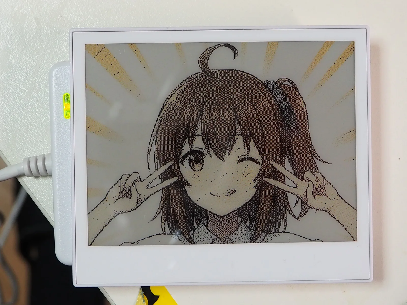
Hair details render in brown tones through fine dithering of red and black dots.
Without a dedicated brown pigment in a 4-color electrophoretic display, halftone error diffusion provides the best achievable visual fidelity.
The PowerShell scripts and flashing instructions used in this verification are available on LiltingChannelLabo.